PDF Downloads
Description
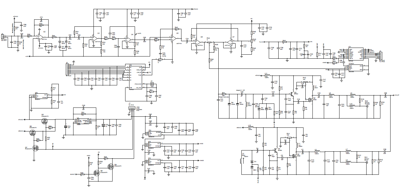
This board contains the modulation shaping and synthesizer circuits. Lets start with the modulation shaping circuit. Audio is applied to J2 a Molex 2 pin header. There are a number of options to set the input impedance for the microphone type being used. These options are set by fitting the resistor required. The options are R50 for electret (powered microphone) R49 for low impedance R49/50 left off for high impedance dynamic microphone. The first amplifier U2 gives again of ~ 12dB and -3dB bandwidth of ~ 3kHz this is followed by a diode limiter D5,6,7,8 to prevent over modulation. The output of the limiter is then passed through an active bandpass filter U3,4 with a 300Hz to 3kHz bandwidth this is then fed to a summing amplifier and mixed with the optional CTCSS signal which is generated by IC5 FX315. The output of the summing amplifier is then fed to the modulation bias and level adjustment circuit which sets the modulation bias a 2.5V dc and splits the signal to feed the TCXO and VCO.
The synthesizer is designed around an Analogue Devices ADF4002 PLL ic. The TCXO is supplied with modulation of ~ 2Vpp siting on 2.5V dc. The TCXO is running at 14.85MHz and is divided by the ADF4002 to give 12.5kHz reference. The TX VCO Q3,Q4 provides the desired transmit frequency between 70MHz and 70.5MHz. The output of the VCO is split using a Wilkinson splitter to feed the ADF4002 RF input and to feed the transmit driver. The TX VCO is fed with ~ 2vpp modulation signal to produce ~ 2.5kHz FM deviation. The loop filter has a cutoff of ~ 300Hz formed using R12,C25,C24,R26,C2,C29 the dc from the loop filter is fed to varicaps D3,D4 BB833 to control the TX VCO frequency.
The Receive VCO Q1,Q2 provide the 25MHz LO for the receiver. Q2 buffer output provides ~ 20mW which is split using a Wilkinson splitter to feed the ADF4002 RF input and LO for the TUF1 mixer. The dc from the loop filter is feed to varicap diode D1 BB201 to control the RX VCO frequency.
CTCSS is available from IC5 a CML FX315 CTCSS encoder. The FX315 requires a 5V supply and a 1MHz crystal X1. The tone is selected from 6 parallel lines which go to the control board to be controlled from the 156F1939 Microcontroller. Tone level is set by RV3.
The power supplies are generated using U1 9V which is switched using Q5,6,7 to provide RXVCO9V and TXVCO9V. IC2,3,5 are used to generate the 5V, 3VADD and 3VDD. IC6 is used to generate the 4.5V virtual ground for U2,3,4.
Links to the VCO prototype tests
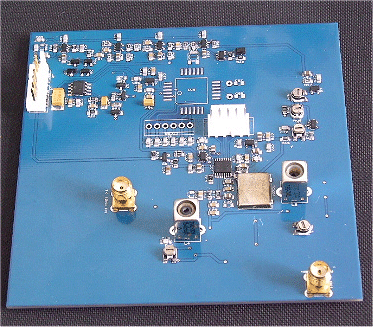
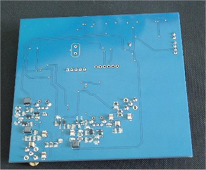
The prototype PCB is a double sided board top side has the power supplies and modulation circuits and the bottom has the RF.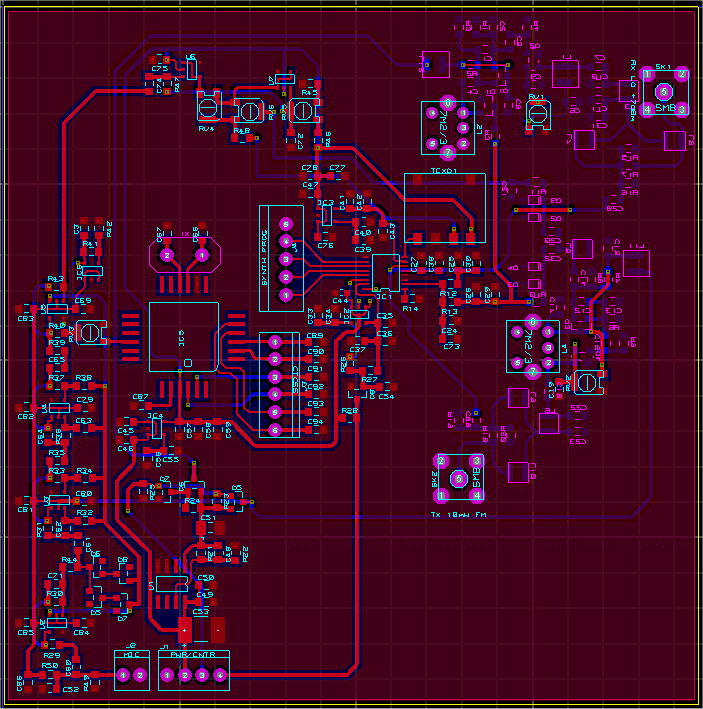
PCB Updates 05/08/16
There have been some updates to the circuit diagram which were discovered during testing of the PCB.
TX9V & RX9V both active. Added a 220k resistor between Q5 and Q7 gate and removed R25. Voltage on Q5 gate was not falling below the -1.3V threshold. Fitting the resister and removing R25 solved the problem. The TXVCO was high in frequency 76MHz min. I found the parallel tank cap was missing from the design. I fitted 18pF which centered the VCO. No TCXO output. The output of the TCXO needed AC coupling and biased at 1.5V at the reference input of the ADF4002. Added 100pF and 2 100k resistors to for a voltage divider. This fixed the problem. The 4.5V opamp artificial ground was going unstable. This was due to R44 being to low raised its value 1k from 100 solved the problem. U6 clipping the top of the audio waveform. This was due to RV3 being at GND added a 150nF cap in series with R40 this solved the problem when CTCSS is fitted. No CTCSS. Connection from pin 20 FX315 to TXE was missing. Also 1M resister need across the crystal to make it oscillate. Link and resistor added this solved the problem.
The PCB layout was not updated The modification were done to the existing PCB because I have a 500 pin limit on the Proteus software I am using and paying £800 to upgrade is not an option at the moment.
PCB Update 16/11/16
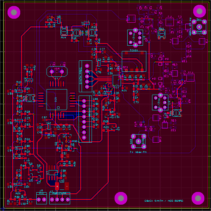
The Updates above have now be add and a new PCB. Also added Q9 to invert the OOL signal. R43 was changed to 200k to increase the deviation to 5kHz. J5 was changed to an 8 way header to allow the CTCSS control signal between the PIC and FX315.
Hand placed, built V1.0 PCB
