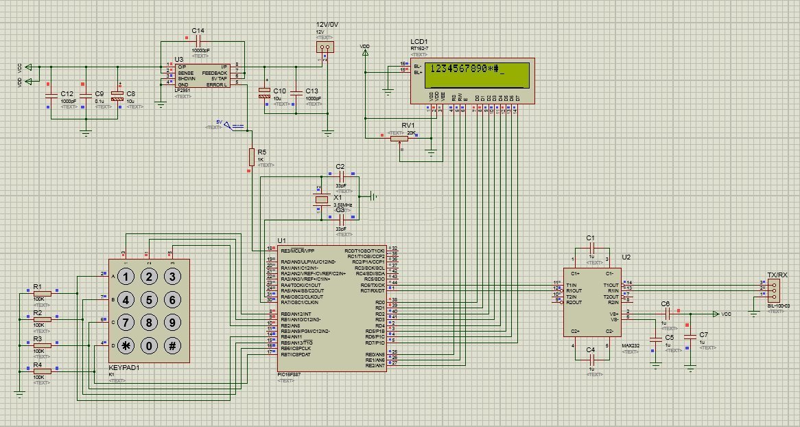
PIC 16F887 with LCD Keypad and Serial Interface
The Keyboard Scanner
The method used to scan the keypad is to set the lower 3 bits of PORTB to Logic (1) and monitor the pin change interrupts on PORTB high nibble. When a key is pressed one of the bits in PORTB high nibble will go high and trigger a PORTB pin change interrupt. When the interrupt is detected PORTB is read and the scan code is compared to look up table to see which button has been pressed. There are two functions in the keypad.c library int ReadKeypad() which returns the scan code and char getChar(int iscan_code) which returns the ascii code for the key pressed.
The LCD Display Driver
The LCD Driver library supports both 4bit and 8bit interface for HD44780 compatible LCD displays. The LCD has been setup on PORTD but can be setup to use any port. Please see the library files for detailed explanation on how to use these libraries. The LCD display chosen for this project is a low power LED backlit 16 x 2 display. You couuld use any HD44780 compatible display. If you use the high voltage back lit displays you will need to amend the circuit to add the high voltage inverter to drive the back light.
Serial Communications
Serial communications is set up on PORTC using RC6 TX and RC7 RX. TX transmits data from the PIC on the serial bus. RX receives data from the serial bus into the PIC. The MAX232 is used to convert the 5V logic signals from the PIC to RS232 compatible signals.

