

G6WCX AUDIO SIGNAL GENERATOR
This project was developed using WPF and C#. The Signal Generator covers the audio spectrum between 1Hz and 20kHz the quality of the signal it produces depends on the bandwidth of the sound channel on the computer its installed on. The current version is 1.00 The program has been compiled to run on Windows 7 or higher with .Net 4.5 assembly installed.
Please Note If you have already read the specification for the WinForms Signal Generator you can skip down to the program operation
Typical specification for the headphone output is :-
Frequency Response = ~20Hz to 20kHz at -3dB = ~40Hz to 19kHz at -1dB (measured at -20dB @ 1khz reference)
Output Level = ~1.5Vrms into >= 25ohms (common headphones ~ 32ohms)
or ~2Vrms into Hi Z >= 40kohms (line level)
"Measured on my laptop 200mVpp into 50 ohms and 2Vpp into Hi Z"
Distortion = THD+N better than -40dB (1kHz sinewave test tone).
The signal generator produces sine, square, triangular, sawtooth waves and pink and white noise. The quality of the square, triangular and sawtooth waveform depends on the actual bandwidth of the audio channel of the computer being used and has been limited to 5kHz. It was shown in tests that signals above ~7kHz tended towards sinewaves. The generator produced a clean sinewave upto 20kHz
Generation of the signals
To generate the signals requires them to be defined mathematically and then sampled over time. The equations used to produce the signals are as follows :-
Because this version of the signal generator is a single channel the phase term can be put to 0 and therefore ignored.
The noise signals are generated from random numbers white noise is broadband noise without any filtering. The white noise is generated by generating random numbers between -1 and 1. Pink noise is filtered noise. To generate pink noise, white noise is passed though a low pass filter with a roll-off at -3dB per octave or 10dB per decade.
The pink noise is generated by using a digital filter which was designed by Paul Kellet details can be found at
http://www.firstpr.com.au/dsp/pink-noise/
Pink Noise Filter
b0 = 0.99886 * b0 + white * 0.0555179
b1 = 0.99332 * b1 + white * 0.0750759
b2 = 0.96900 * b2 + white * 0.1538520
b3 = 0.86650 * b3 + white * 0.3104856
b4 = 0.55000 * b4 + white * 0.5329522
b5 = -0.7616 * b5 - white * 0.0168980
pink = b0 + b1 + b2 + b3 + b4 + b5 + b6 + white * 0.5362
b6 = white * 0.115926
Generating The Wave File
The method used to generate the signals is to produce a wave in file in memory and loop over it to give a continuous signal. The wave file consists of header information and PCM data representing the waveform to be played.
The default sample rate used is 44100 samples per second and encoded into 16 bit samples. The specification for 16 bit samples states the samples shall be signed integers and vary between -32,768 to 32,767. The wave file data format is a PCM(Pulse Code Modulation). This can be generated using a for loop to build the data eg:-
int amp = 32767;
int samples = 44100;
double f(w) = 2*Math.PI*f; // where f is the required frequency eg; 1kHz
// Setup a new memory stream to write binary data to
var mStrm = new MemoryStream();
BinaryWriter mWriter = new BinaryWriter(mStrm);
for (int step = 0; step < samples; step++)
{
short s = (short)(amp * Math.Sin(f(w) * (double)step));
mWriter.Write(s);
}
The program allow the sample rate to be change on all waveforms except for sweep mode and pink noise this is because the pink noise filter and sweep mode are optimized for a sample rate of 44100Hz per second. It is possible to vary the sample rate between 8000 and 192000 samples per second if your computer supports it. Using higher sample rates will reduce the distortion on the square, triangular, sawtooth waves.
The wave stream is then played using the PlaySound API which turns the wave stream into sound and routed to the default sound option.


Program Operation
The program has been built using the Windows Presentation Foundation C# and XAML using Microsoft Blend 2015. The signal generator engine code is the same code I wrote for the WinForms version of the signal generator.
The controls have been written into a custom control library called CustomControlLibrary.dll. The controls in the library are an LCD display, Knob, Panel Meter, LED, and a Switch.
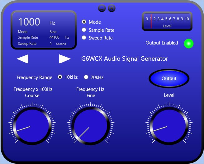
The signal generator program lets you select a frequency between 1Hz and 20kHz sinewave in two ranges and Sweep across the frequency range. The upper frequency limit for the square, triangular and sawtooth waves is 5kHz. It will also generates Pink and White Noise and allows you to adjust the level of the output signal.
The selected options for the signal generator are displayed on the LCD and can be adjusted using the buttons to the right of the LCD and the selection buttons below the LCD can be used to scan through options.
The frequency is adjusted using two knobs one is used for course adjustment of 100Hz steps and the second is used for fine adjustment of 1Hz steps.
You can select one of the two frequency ranges using the frequency range buttons. The two ranges are 10kHz or 20kHz. The 20kHz range disables the square, triangular and sawtooth waveforms.
The wave shape can be changed from sine, square, triangular, sawtooth and white and pink noise and sweep mode by selecting Mode in the option buttons and using the selection buttons below the LCD.
You can select a different sample rate by selecting Sample Rate in the option buttons and using the selection buttons below the LCD. When changing the sample rate select one which is at lease twice the highest frequency you want to use. Choosing a higher sample rate will improve the jitter on the square, and sawtooth waveforms. You will not be able to change the sample rate when you have selected pink noise or the sweep option.
The sweep function will sweep between 1Hz and 20kHz
The sweep time can set between 1 and 5 second by selecting Sweep Rate in the option buttons and using the selection buttons below the LCD.
Every time you change frequency, wave shape, sample rate or sweep time a new waveform is written into memory.
You can change the amplitude of the waveform with the level control the maximum will be around 2Vrms depending on the load you are driving. Note you should not connect a load < 25ohms to you headphone socket it could damage your computer.
The meter will show the level into the mixer and not the final level which is set by the master volume control located on the mixer. This is usually located in the start tray. Note If the master volume control is set to maximum the meter will show actual output level.
Download
Acknowledgements
Paul Kellet for development of the Pink Noise Filter
Written by Desmond Mardle BSc MIEEE
Date 18/09/15