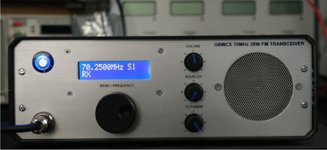

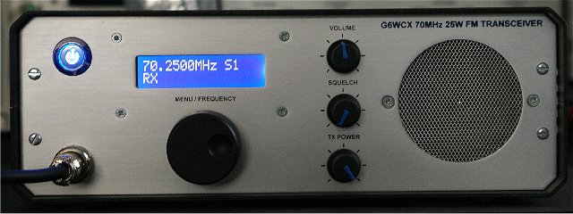
Front Panel
Rear Panel
The transceiver was built into an anodized aluminum case which came in 6 sections the front and rear panels which are silver anodized the two lids which are black anodized and two aluminum sides. 1.5mm aluminum sheet was used to make the chassis to mount the pcb's. The chassis was cut to size allowing for the front panel controls. Blank pcb's were the stuck on the chassis with doubles sided tape and the hole drilled. The pcb's were then mounted on the chassis using 10mm spacers and M3 screws and washers. The RF boards are mounted on the top of the chassis and the control pcb mounted on the underside.
The front panel components were the mounted. The rear panel had the heat-sink and connectors mounted. The chassis was fitted between the two sides and the front and rear panels were screwed to the side panels I then started to wire the connections between the pcb's and front panel. Molex header 2.54mm connectors are used to make the switching and low frequency connections between the boards and front panel components. 5 pin headers are soldered on the potentiometer connections to allow them to be ease of connection. The RF connection are made using RG319 and SMA connectors I got pre made 15cm cables from ebay. This makes it easy to access the pcb's if necessary. The PA was fitting is the tricky bit. The PA module is inserted into the main RF pcb and the bolted to the rear panel using M3 screws nuts and washers earthing straps are the filled from the RF pcb to the earth terminals of the PA and two extra straps between the rear panel and the screws at rear edge of the RF pcb. I used solder braid to make the straps and fitted M3 solder tags were screws were available. The braid was soldered to give it some rigidity to help keep the PA in place so it could be soldered to the RF pcb. I also made some spacers from 1.6mm copper clad and secured them under the screws at the edge of the board rear panel screws and set them flush with the top of the RF pcb. This was done to make sure the PA was the right height above the pcb. To gain access the the underside of the RF pcb you need to unplug the front panel components from the pcb's. The turned over the chassis so the bottom is on top then you need to remove the 4 screws securing the RF PCB to the chassis. Slide the rear panel and chassis back revealing the underside of the RF pcb then use two of the screws to secure the RF board to the chassis while you checked alignment and solder the PA to the pcb. Once the PA is soldered in place and the leads trimmed you can remove the two screws holding the RF board in place and slide the rear panel back and secure the RF pcb to the chassis and fit the rear panel screws. Now the front panel components can be connected to the pcb's again.
I used a crimp tool to make the connections to the Molex pins. It save lot of time I got the crimp tool from ebay for ~ £40 it was well worth the money.
Now the transceiver is built it needs to be tested. I set the drive from the synthesizer pcb to 4mW this was enough to produce ~ 50mW from the drive transistor to drive the PA block in class C and give ~ 30W. I padded the power control to give a power range between 0 and 25W at the antenna socket. The drive band-pass filter was aligned before the RF board was fitted with a sweep generator and a spectrum analyzer.
The spurious out was then checked on my spectrum analyzer. I used a 30dB pad between the output of the radio and the spectrum analyzer. I had 20dB 100W pad I salvaged from a old radio test-set and 5W 10dB pad. There were no detectable harmonics @ -40dBm. to measure lower down I need to build a notch filter to notch out the carrier.
I decided to connect an antenna and put a sniffer on the spectrum analyzer to see what the radiated signal looked like the harmonics were at least 60dB below the carrier the second was not visible so I was happy with that.
The modulation setup on the synthesizer pcb was carried out before the board was fitted. The modulation is setup by applying an audio signal from a signal generator to the microphone input at a set amplitude and a low and high frequency and adjusting two trimmers one for the low frequency and one for the high frequency so the levels are the same. this will give a frequency response 300Hz and 3kHz. The deviation has been set for 12.5kHz channel spacing 3kHz peak deviation.
The frequency stability is controlled by a tcxo with a 5ppm drift over temperature it also has +/- 30ppm pulling range which is why it was used in the dual point modulator. The center frequency is adjusted by the tcxo. This was expensive @ ~ £35 for small quantity's. Luckily I had one in an old piece of equipment.
The receiver was aligned before the main RF board was fitted. The receiver alignment involved setting up the 70MHz band-pass filter with a spectrum analyzer with a sweep generator. Injecting a 45MHz modulated signal eg: 1kHz at 3kHz deviation and adjusting the discriminator coil for maximum recovered audio with minimum distortion to achieve minimum distortion the trimmer between the 45MHz filter was adjusted for minimum distortion this can be achieved by adjusting for best SINAD. Finally the front end amplifier was aligned to give best SINAD. The receiver achieved -120dBm for 12dB SINAD which is quite good.
The control pcb is mounted on the underside to minimize interference to the receiver. The micro controller has been programmed using C. The radio is currently undergoing field trials with the software to see how it performs. Results so far have been good.
Top
The Transceiver
Bottom