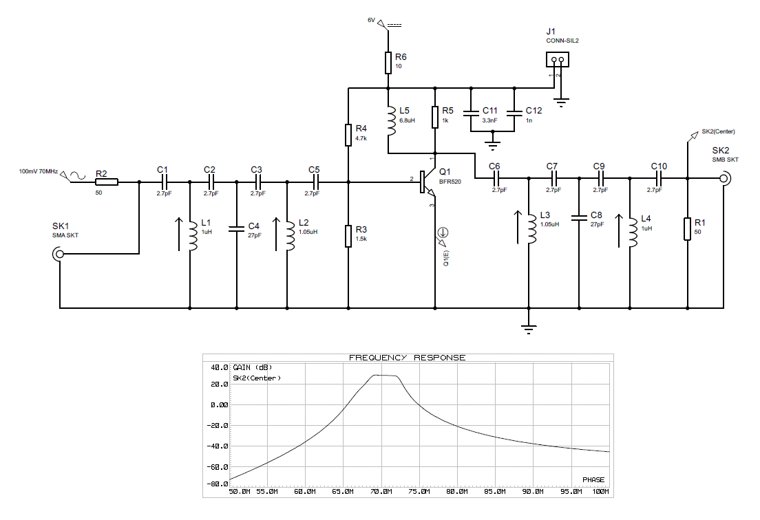
The Spectrum Analyzer picture below shows the actual measured frequency response. It has a ~2MHz bandwidth and 23dB of gain.. The only difference in the circuit diagram above is I changed the inductors to 820nH as the original 1uH inductors would only tune to 66MHz. I measured the noise figure using the subtraction method in a 10kiHz bandwidth and was surprised to see it was 11dB. The filter sections have a ~6dB insertion loss. I checked the calculated noise figure in Zmztch which gave me ~8dB. The amplifier has good large signal handling. I will probably use another low noise pre-amp and switch between the two.. I have now designed a new amplifier using a BF998 MOSFET.
The 1dB compression point has been measured @ 12.5dBm
To measure the 1dB compression point apply a single tone signal and increase its level until the gain drops by 1dB. The output power at that point will be the 1dB compression point.
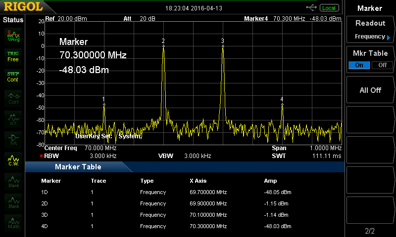
The 3rd order intercept has been measured @ ~22.5dBm
The 3rd order intercept point is calculated by using the measurements from the third order products generated by applying 2 tones in the passband of the amplifier equally spaced from the center frequency. The two tones used in this test were 69.9MHz and 70.1MHz the amplifier should be operated in its linear region.
IP3 = P1 + 0.5(P1 - P3)
P1 = fundamental P3 = 3rd order component.
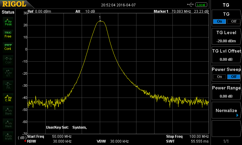
Frequency Response
3rd order products
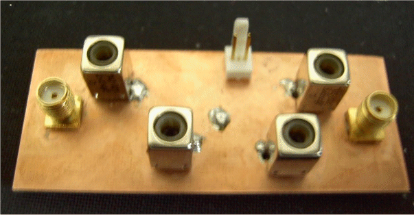
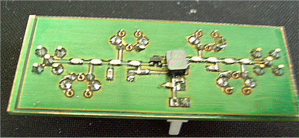
Milled Prototype PCB
